 About:
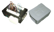
This is my home automation system. 8 home appliances, and countless low voltage devices can be attached to any
of its many output terminals and controlled. It was designed to interface with a computer for real-time local or
internet based control. Because the ac appliance control portion of the device was made from x-10 wireless modules,
my home automation system retains the ability to be controlled by wireless remote as well.
This project has been in the works for a very long time. It was constantly being revised, redesigned, and reassembled.
It wasn't until recently, however, that it took its final form. Past prototypes existed solely as circuits on a bread
board and dangerously interconnected components held together with alligator clips. This is the first time that
controlling circuits have been properly fabricated and exterior housings assembled to enclose all the components
into a visually appealing final product.
The home automation system exists as 2 separate interconnectable devices referred to as phase one and phase two.
The device referred to as phase one was built first and is the primary unit in the whole system. It is even capable
of operating correctly on it's own. This is the unit that connects to the computer. Phase 2, which is physcally much
larger, is a sub unit of phase 1. It can not opperate by it self, in fact it attaches to phase 1 via a 6 conductor
phone line and contains no computer connectors of it's own.
 Phase I:
Phase 1 is only about 8"x5"x4". Since this unit is the component that connects to the computer and
the external power supply, it is capable of opperating on it's own. This unit's purpose is for switching
low voltage devices. It contains both momentary and reversable switching connections and can accommodate
up to 16 devices. It's digital logic is executed by a 4 to16 demultiplexor (dmux) which takes in a 4 bit
binary word from the controlling computer's parallel port. The dmux takes the binary coded input and sends
a binary-high to one of its output pins. The output pins are attached to the various relays and relay
circuitsfor the voltage switching.


 Phase II:
Phase 2 is physically much larger. In addition to containing a dmux for binary coded decimal interpretation
and relays for low voltage switching, it also houses all the surge strips and x-10 modules for the high voltage
ac switching. Like phase one, it's logic is executed by one chip. Unlike phase one, however, this unit is
specifically designed to switch normal household ac appliences. Also, phase 1 has all momentary conenctions,
phase 2 has all latching connections so that the appliences may stay on or off for long periods of time with
out placing strain on any of the internal components. For convinience, AC outlets have been placed on the dorsal
side of the device. In the front there is a phone jack so that it can connect with phase 1. The 6-conductor phone
line simply carries 4 more data lines attached directly to the computers parallel port connector located inside of
phase 1, and the power needed to drive its circuitry.


 Components:

|
This is a relay control board with 2 high voltage reversing channels. This unit was placed into phase 1.
|


|
Here is a low voltage reversing relay board, also for phase 1.
|


|
This is phase 1's primary logic controller. The board pictured here contains the demultiplexor
and four relays attached directly to the demux's outputs. The diodes are present to prevent cross
shorting because the demux's outputs are high by default.
|


|
This is phase 2's primary logic controller. Even though only 8 outputs are utilized, all 16 output
pins on the demux were paired with diodes for future expansion.
|


|
The back side of phase 2's relay based x-10 module tripping board.
|


|
The front side of the board above.
|


|
This is all the circuit based components of phase 2 all interconnected before they were attached
to the rest of the system.
|

 X-10 Modules:
The x-10 modules were used inside of phase 2 so that AC applience switching can be executed by either computer or
wireless controller. On their own, the x-10s can only respond to their respective hand held remote. With only a few
modifications, however, they can be made computer responsive. Each individual module contains a large latching relay,
which turns its AC appliance on or off. The relay toggles its open/closed state with every electrical pulse it receives.
This pulse is emitted whenever a "switch" turns on. In this case, that "switch" is a transistor. So to make this module
computer responsive, the only modification one would have to make is to solder one wire to this transistors emitter, and
one to it's collector. Since by default the transistor is an "open circuit", all you have to do to deliver the pulse to
the relay is short the newly soldered wires. Touching them together will bypass the transistor, give the relay its electrical
pulse, thus toggling the on/off state of the ac appliance.
In phase 2 I have my own smaller relay placed between those 2 soldered wires. My relay can be tripped with as little as 5v.
This allowed me to directly attach the tripping relays to the dmux.
 
|


 About:
 Phase I:


 Phase II:


 Components:


 X-10 Modules:


 Viewer Comments
 Leave A Comment