Last Updated
    2 / 28 / 12
Original Site


    Path: BinaryBedlam > Krill Labs > projects > Low Voltage > Home Automation System V2.0    


Home Automation System V2.0
Developed:        
3/1/2006


Status:
Complete / In-Use


Summary:
My second more practical home automation system.
-OVERVIEW-


About:
       Finally! The much anticipated upgrade to my famous home automation systems! This new version is far superior to it's predecessor. It supports many more channels, has a complex "finite state machine" that includes memory states, uses ethernet jacks for easier expansion, and is run with a much more user friendly windows application.

       To get more specific, there are 2 types of channels with this device. Buffered and unbuffered. There are 24 buffered states. These are the neatest, but the hardest to implement because their memory uses a bunch of flip flop chips. There are 48 unbuffered channels. These are all momentary style connections. Both types of connections are ported to the ethernet jacks on the front where I can connect up any of my expansion modules. The modules range from light controllers to motor drivers, I even have a remote spy camera module.


Initial Testing:
Here are some pictures of the initial stages of the design where most of the cirucits were being tested on a breadboard in a controlled environment.


Controller Construction:
In these pictures the bulk of the circuit testing was done and the main boards were fully soldered up. This is the assembly of the main central unit.


2 axis Zoom Spy Camera Module
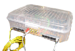
       This is the coolest module for my home automation system v2.0. I took an old huge vhs camcorder, ripped it apart and kept only what was needed to make it function as just a video source. I then put those guts into a tupperware container, mounted it to 2 car motors (wind shield and power window), and built a control circuit for interfacing it with the main home automation system.


Other Device Modules:

       Here is the ctl circuit for the motor driver module.


       The guts to the completed motor driver module. Those cubes are automotive relays.


       Here is the finished motor driver module.


       This is the ctl cirucit for a lamp driver module.


       This is the back of the ctl cirucit for a lamp driver module.


       Here are some lamp driver modules.


Viewer Comments


Leave A Comment


NAME: REMARK:


BinaryBedlam's Basic Web Development 2010© .
Created by Dan Krill of BinaryBedlam ; Krill Labs and any of its subsidiary components, which include but are not limited to: Graphical Design and Layout, Images, and Decals;
are the property of the owner and should not be used with out expressed written consent from the web administrator .