 About:
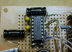
I ran into quite a number of issues when trying to use the Max232 chip. I found lots of articles online regarding how to wire the thing, but none cover any of the details on properly using it. It's a simple circuit to build and integrate, but there are a bunch of prerequisites to actually making it work. And if I didn't have an Oscilloscope, I probably would have never figured it out myself.
 Establishing a Baseline:

|
First off, here is what a waveform from a computer's serial port should look like. I am transmitting [space] & "." back to back. Note the amplitudes, 1 = -15v and 0 = 15v.
|


|
Here is the same waveform as produced directly by my Pic Processor. The amplitudes are now 1 = 0v and 0 = 5v.
|

 Notes So Far:
RS-232: idles on logic 1, low = 1, transmits a logic 0 to signify a start, high = 0, and sends the LCB first.
You DO NOT need the MAX232 chip to interface the processor directly to the computer's serial port. A PC's comm port is capable of translating the TTL levels with out any additional hardware. Just make sure the PIC is using non-inverted comms.
Also, When building the MAX232 circuit, it is not necessary to use consistent capacitors. I didn't have any 1uF caps in my stock, so I had to go to Radio Shack. And even "The Shack" was on the short side, they only had 2 tantalum and 2 electrolytic caps at this value, and I needed 4, so I had to mix and match.
 Hooking up the Converter:
Now here is the waveform out of the MAX232 converter (as produced by the PIC). The amplitudes are now 1 = -10v and 0 = 10v. But look closer at the waveform, it's upside down! This chip inverts the signal. No one ever mentioned that!
To correct for that, you have to invert the comms at the PIC to compensate. Two inverts make a right. This is usually simply done when defining your system type, i.e. instead of using N9600, try T9600 (T=true, N=non-inverted).
Also note that the waveform idles low prior to the sequence, but idles high after the sequence. This is also a problem. This was caused by another section of my program blindly setting all of PortC to 0. Keep in mind, the Rx and Tx pins are also on PortC. To account for this, make sure the Transmit pin is initialized high then never reference it again in your program. Now that we are using inverted comms, the PIC's Receive pin has to be high for steady state (not receiving anything), and it's transmit pin also needs to remain high, so don't accidently toggle it to 0 in your code like I did, because if you do, the receiving end wont be able to tell where the sequence actually starts.

|

 After the Adjustments:

|
Here is the waveform of the converter after initializing the Tx pin high and inverting all the comms. Much Nicer!
|


|
Here is an explanation of the waveform.
|

 More Notes:
Another thing to watch out for, If your program is supposed to simply echo back the bytes it receives from say hyper terminal, but it seems to come back garbled, yet bytes transmitted on the PIC's own accord, like a boot up sequence seem to come back ok, it is more than likely because you are attempting to transmit too close to a receive. Try placing a 500us pause between the part of your code that receives the string and the part that echoes it back out.


 About:
 Establishing a Baseline:


 Notes So Far:
 Hooking up the Converter:

 After the Adjustments:


 More Notes:
 Viewer Comments
 Leave A Comment