 About:
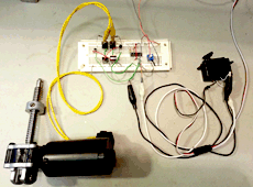
If you need to control a large motor but want it to have the same position control of a servo, you don't have to throw crazy amounts of money at it. You can actually have a plain old servo it self drive a large motor. This way you can feed the servo a desired position via a PWM signal, the servo tells the large motor which direction to move, and as the servo arm/pot is nudged back to equalibrium, the motor is brought to a stop.
 Theory:
You can NOT directly connect your servo motor leads to a lot of things, not a larger motor because the tiny circuit can only drive tiny motors, and not even a typical H-bridge. Here's why, if you connect the servo motor leads to an o-scope, you'll see that the pulses not only change polarity depending on the direction it needs to turn the motor, but at rest (when the pot position exactly matches the PWM) it sits both motor leads outputs at 2.5 volts, NOT at ground. Now lets look at just one side of your H-bridge, and lets assume your driving it at 12v, its got a PNP and NPN transister. The NPN is turned "on" when it gets anything above 0, the PNP is backwards, it is turned on with ANYTHING below 12, so, if you give your H-bridge 2.5 volts, BOTH the PNP and NPN are on at the same time! Thats a direct short to ground, it would fry your power transistors! Connect the motor leads to a signal modifyer first to ensure that your h-bridge gets a control signal of exactly 0 and Vmot.

 Procedure:
So the first step is to take apart the servo, remove the second to last stage gear so the lever arm is free to spin yet still moves the POT. Next remove the motor, snipping the lead wires at the base of the motor. They will probably be mega short so maybe solder longer wire segments to them, drill tiny holes in the side of the servo to run these 2 wires out, then put the whole thing back to gether
Ok, what do you do with these motor leads? The motor output of servos can NOT be directly attached to an H-bridge because the square wave output signals do not center at ground, they center at 2.5, so there is technically never an "off" moment (in the eyes of a transister). The servos do this because applying a mid voltage evenly to both sides of a motor prevents it from free spinning, this is also called, "Breaking". To use these signals in most motor driving applications, you could run both outputs through a comapator or schmit trigger to generate a new square wave that oscillates between 0 and V-motor-max.
Now that your 2 control signals oscillate between the proper voltages you can attach it to anything, like an H-bridge. See the below diagram to see examples of attaching both a mosfet and transistor based h-bridge to the comparitors for a fully functional externalized servo mechanism.

 Related Video:


 About:
 Theory:

 Procedure:


 Related Video:
 Viewer Comments
 Leave A Comment